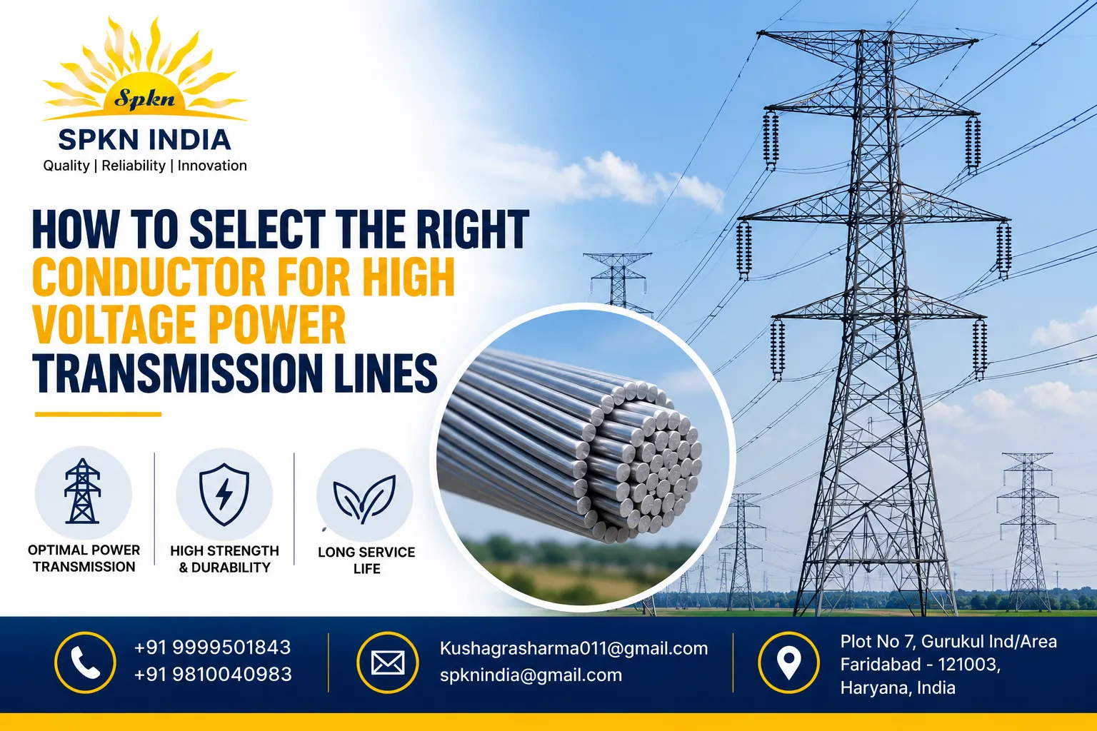
Selecting the right conductor is not a simple matter of picking a size off a catalogue. It involves balancing electrical performance, mechanical strength, thermal behavior, and long-term durability against the specific voltage class, span length, and environmental conditions of the route. Get it wrong, and the consequences range from excessive line losses to sag related clearance violations that trigger flashovers during hot summer loading.
Why Conductor Selection Decisions Carry Long-Term Consequences
I have reviewed transmission line designs where the conductor was selected primarily to meet current-carrying requirements at the design stage, without adequately accounting for future load growth. Within eight to ten years, the line was operating close to its thermal limit, forcing an expensive reconductoring project that could have been avoided with slightly more conservative sizing at the outset.
High voltage transmission lines typically stay in service for thirty to fifty years. A conductor selection made today has to account for:
- Present and forecast future load current
- Voltage drop limits over the line length
- Mechanical loading from wind, ice, and temperature variation
- Corona and radio interference performance at the operating voltage
- Long-term corrosion resistance for the specific route environment
Types of Conductors Used in Transmission Line Design
All Aluminium Conductor (AAC)
Pure aluminium strands with no steel reinforcement. Good conductivity but lower tensile strength, generally used for shorter spans or lower voltage distribution rather than long high tension power line voltage routes.
All Aluminium Alloy Conductor (AAAC)
Made from an aluminium magnesium silicon alloy, offering a better strength to weight ratio than AAC while maintaining good conductivity. Commonly used where corrosion resistance is a priority, such as coastal transmission corridors.
Aluminium Conductor Steel Reinforced (ACSR)
The most widely used conductor type for high voltage transmission lines in India. A steel core provides mechanical strength while the surrounding aluminium strands carry the current. ACSR remains the default choice for most 66kV, 132kV, 220kV, and 400kV transmission projects because of its proven strength to weight performance and cost efficiency.
All Aluminium Alloy Conductor Reinforced (AACSR)
Combines alloy strands with a steel or alloy core for applications requiring higher tensile strength than standard ACSR, often used for river crossings or long spans with limited tower support points.
Comparison of Common Conductor Types
| Conductor Type | Conductivity | Tensile Strength | Corrosion Resistance | Typical Use Case |
|---|---|---|---|---|
| AAC | High | Low | Moderate | Short spans, distribution level |
| AAAC | Moderate to High | Moderate | Good | Coastal routes, moderate spans |
| ACSR | High | High | Moderate, needs galvanized steel core protection | Standard transmission lines across voltage classes |
| AACSR | Moderate | Very High | Good | Long spans, river crossings, high mechanical stress zones |
Step-by-Step Approach to Selecting the Right Conductor
Step 1: Determine the System Voltage Class
The voltage class, whether it falls under sub-transmission or extra high voltage, sets the baseline requirements for clearance, insulation coordination, and corona performance.
Step 2: Calculate the Required Current Carrying Capacity
Base this on present peak load plus a reasonable growth margin, typically evaluated over a fifteen to twenty year planning horizon, factoring in ambient temperature and conductor operating temperature limits.
Step 3: Evaluate Voltage Drop Over the Line Length
Longer lines with smaller conductor cross sections experience higher voltage drop. For long electric transmission line voltages routes, a slightly larger conductor size may be justified purely to keep voltage regulation within acceptable limits, independent of thermal current rating.
Step 4: Assess Mechanical Loading Conditions
Wind loading, ice loading in applicable regions, and span length between towers determine the required tensile strength and sag behavior of the selected conductor.
Step 5: Check Corona and Radio Interference Performance
At higher voltage classes, conductor diameter affects the surface electric field gradient, which influences corona discharge and associated audible noise and radio interference. Bundle conductor configurations, using two or more sub-conductors per phase, are often used at 400kV and above to manage this.
Step 6: Confirm Standards Compliance
Verify the selected conductor meets IS 398 (parts 1 through 5 depending on conductor type), relevant IEC 61089 provisions where applicable, and any specific CEA guidelines or Power Grid specifications referenced in the project scope.
Sag and Tension: Why This Calculation Cannot Be Skipped
Sag is the vertical distance a conductor droops between two support points due to its own weight, and it changes with temperature and mechanical loading. Getting sag and tension calculations wrong is one of the most common causes of ground clearance violations found during line audits.
Key factors influencing sag and tension:
- Conductor weight per unit length
- Span length between towers
- Ambient and conductor operating temperature
- Wind and ice loading conditions specific to the route
- Initial stringing tension applied during installation
In my experience conducting line clearance surveys, sag related issues often trace back to stringing tension that was not properly recorded or verified against the design sag tension chart during construction, rather than a fundamental conductor sizing error.
Electrical and Mechanical Properties That Matter Most
| Property | Why It Matters |
|---|---|
| Resistance per km | Directly affects line losses and voltage drop |
| Cross sectional area | Determines current carrying capacity |
| Ultimate tensile strength | Determines mechanical safety margin under loading |
| Stranding configuration | Affects flexibility, ease of installation, and surface smoothness for corona control |
| Coefficient of linear expansion | Influences sag behavior across temperature variation |
| Corrosion resistance | Determines service life, particularly in coastal or industrial pollution zones |
Industry Standards Governing Conductor Selection
Reliable conductor selection depends on adherence to established standards rather than manufacturer claims alone:
- IS 398 covers specifications for ACSR, AAC, and AAAC conductors used in India
- IEC 61089 provides international specifications for round wire concentric lay overhead electrical stranded conductors
- CBIP guidelines offer practical recommendations for transmission line design parameters specific to Indian conditions
- CEA guidelines define technical standards for construction of electrical plants and electric lines, including clearance and loading requirements
- BIS certification confirms the conductor meets mandatory Indian quality benchmarks
Installation Considerations for Transmission Line Conductors
- Stringing tension must match the design sag tension chart for the specific span and temperature condition at the time of stringing
- Conductor joints and mid-span compressions must use manufacturer-approved fittings rated for the conductor's mechanical and electrical performance
- Adequate ground clearance must be verified at maximum sag condition, not just at installation temperature
- Bundle spacers are required for bundle conductor configurations to prevent sub-conductor clashing under wind-induced oscillation
- Vibration dampers should be installed at appropriate points to reduce aeolian vibration fatigue on the conductor and at termination points
Common Mistakes in Conductor Selection
- Sizing the conductor for present load only, without adequate margin for future demand growth
- Selecting conductor type without accounting for the specific corrosion environment of the route, such as coastal or industrial pollution zones
- Underestimating span-specific mechanical loading, particularly in regions prone to high wind or ice
- Overlooking corona performance requirements at higher voltage classes, leading to excessive audible noise complaints after commissioning
- Failing to verify that selected conductor fittings and hardware are rated for the specific conductor size and type
Maintenance and Inspection Checklist
- Periodic visual inspection for strand damage, corrosion, or bird caging along accessible spans
- Infrared thermography during scheduled maintenance to detect abnormal heating at joints and terminations
- Sag verification at select spans to confirm ground clearance remains within acceptable limits over time
- Inspection of vibration dampers and bundle spacers for wear or displacement
- Corrosion assessment at coastal or industrially exposed sections, with more frequent checks than inland routes
Safety warning: any inspection or maintenance activity near energized high tension power line voltage conductors must follow proper approach distance and de-energization or live line work protocols as applicable, performed only by trained and authorized personnel.
Future Trends in Conductor Technology
High temperature low sag conductors, using advanced core materials that allow higher operating temperatures with reduced thermal sag compared to conventional ACSR, are gaining attention for uprating existing transmission corridors without full tower replacement. This approach is particularly relevant where right-of-way constraints make new line construction difficult, allowing utilities to increase capacity on existing transmission lines infrastructure.
Why Working with an Experienced Equipment Supplier Matters
Conductor selection does not happen in isolation. It has to be coordinated with the tower design, insulator string selection, and hardware fittings used across the line. A supplier that understands this full system, rather than just supplying a single component, helps avoid compatibility issues discovered late in the construction phase.
SPKN India supports EPC contractors and utilities with Transmission Line Hardware, Substation Equipment, Electrical Isolators, Lightning Arresters, and Earthing solutions that complement conductor selection decisions across transmission line projects. For teams evaluating complete line design packages, coordinating conductor, insulator, and hardware selection with a single technically capable supplier often reduces integration issues during construction and commissioning.
Conclusion
Selecting the right conductor for high voltage power transmission lines requires balancing electrical performance, mechanical strength, corrosion resistance, and long-term load growth rather than focusing on a single specification in isolation. Sag and tension calculations, standards compliance, and proper coordination with insulators and hardware all play a role in whether a transmission line performs reliably for its full design life. For engineers and project teams working on transmission line design and procurement, SPKN India provides supporting equipment and technical coordination to help ensure conductor and hardware selections work together as a complete, standards-compliant system.